LYNKED Thermal Energy Meter (LYKH Series)
TECHNICAL MANUAL
Published November 11, 2026 • Last updated November 11, 2026 (v1.1)
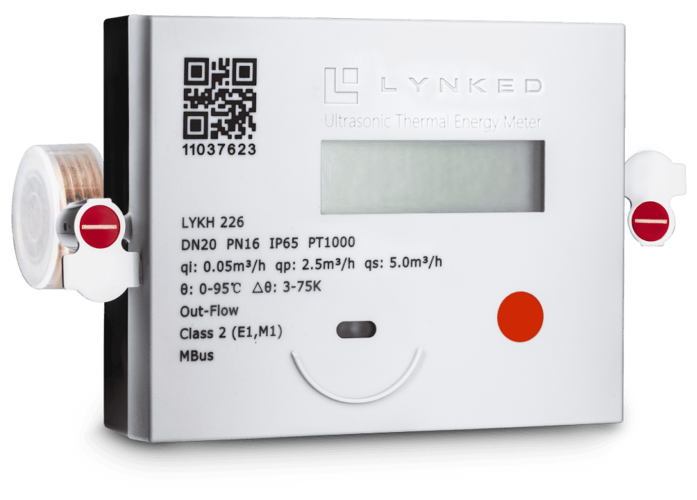
1. Specifications
1.1 Size & Flow Matrix
The LYKH series supports a range of pipe sizes, flow rates, and flange geometries.
| DN (mm) | ASME (in) | Qp (m³/h) | Qs (m³/h) | Qi (m³/h) | Flange OD (mm) | Length (mm) | Bolt connection |
|---|---|---|---|---|---|---|---|
| DN50 | 2.0 | 15 | 30 | 0.3 | 165 | 200 | 4 × M16 |
| DN65 | 2 ½ | 25 | 50 | 0.5 | 185 | 200 | 4 × M16 |
| DN80 | 3.0 | 40 | 80 | 0.8 | 200 | 225 | 8 × M16 |
| DN100 | 4.0 | 60 | 120 | 1.2 | 220 | 250 | 8 × M16 |
| DN125 | 5.0* | 100 | 200 | 2.0 | 250 | 250 | 8 × M16 |
| DN150 | 6.0 | 150 | 300 | 3.0 | 280 | 300 | 8 × M20 |
| DN200 | 8.0 | 200 | 400 | 4.0 | 335 | 345 | 12 × M20 |
| DN250 | 10.0 | 400 | 800 | 8.0 | 405 | 445 | 12 × M24 |
| DN300 | 12.0* | 600 | 1200 | 12.0 | 460 | 500 | 12 × M24 |
| DN350 | 14.0* | 800 | 1600 | 16.0 | 520 | 500 | 16 × M24 |
| DN400 | 16.0* | 1000 | 2000 | 20.0 | 580 | 600 | 16 × M27 |
*Asterisks indicate estimated nominal ASME flange conversions based on metric pipeline standards. All physical connections utilize CL 150 ASME B16.5 flanges rated to PN16 (1.6 MPa).
1.2 Operational & Electrical Baseline Specifications
| Operational parameter | Design rating / baseline value |
|---|---|
| Temperature range (medium) | 1 °C ~ 150 °C |
| Temperature difference range (ΔT) | 3 K ~ 95 K |
| Temperature sensor type | Pt1000 platinum RTD, certified paired set |
| Metrological accuracy class | Class 2 (EN 1434 compliant) |
| Maximum working pressure | 1.6 MPa (PN16 standard) |
| Pressure loss | P < 25 kPa at nominal flow rate Qp |
| Ingress protection rating | IP68 |
| Battery | Lithium 3.6 VDC |
| Standard operating temperature | −30 °C ~ 55 °C (storage and electronics) |
| Wired communication options | M-Bus, RS-485, pulse output |
| Wireless communication options | LoRaWAN (EU433, EU868, IN865, US915), Sigfox, 4G CAT1, NB-IoT |
| Standard display unit options | kWh, MWh, GJ — factory programmable or configurable |
LYKH Series Technical Specifications Sheet
Dimensions, flow ranges, electrical ratings, and interface specs
2. Safety Information
Read this manual in full before installation or service. Calibration integrity, metrological classification, and warranty are all contingent on obeying the environmental, electrical, and hydraulic recommendations in this document.
Explosion Hazard
The calculator contains a battery. Electric welding and flame cutting near the meter can rupture the cell, causing an explosion and serious injury, and will damage the internal digital sensors.
- Do not perform electric welding or flame cutting on or near an installed meter.
- Complete all pipeline welding before mounting the meter.
- Do not short, puncture, crush, disassemble, heat, or incinerate the battery.
- Battery replacement is restricted to authorized service personnel.
- Dispose of used cells in accordance with local, provincial, state, and federal regulations.
Pressure Hazard
The pipeline operates at up to PN16 (1.6 MPa / 232 psi). Removing a meter from a pressurized line can release scalding fluid under pressure and cause serious injury.
- Isolate the meter using the upstream and downstream valves, then fully depressurize and drain the section before loosening any flange bolt.
- Verify the pipeline system is rated to PN16 before commissioning.
- Follow your site's energy-isolation and lockout/tagout procedure.
Burn Hazard
Medium temperature can reach 150 °C (302 °F). Meter bodies, pipework, and temperature sensor pockets remain hot after shutdown and can cause severe burns.
- Allow the system to cool before servicing, and wear appropriate personal protective equipment.
- Do not touch the flow sensor body or sensor pockets during operation.
Crush and drop hazard during handling
Larger sizes in this series are heavy cast assemblies. Dropping a meter can cause injury and may damage the meter.
- Never lift, carry, or support the meter by its plastic calculator head or by any sensor cable.
- Always support the device by its cast metal flow sensor body.
- Use mechanical lifting equipment where the assembly exceeds safe manual handling limits.
Seals, calibration, and warranty
All factory-installed lead seals and safety marks on the meter housing should remain fully intact. Damaging, tampering with, or removing any seal voids the warranty.
Installation conditions
- The heating circuit should not exceed a maximum operating pressure of PN16 (1.6 MPa).
- Install indoors in a closed, climate-controlled environment with non-condensing humidity, between 5 °C and 55 °C.
- Draw all control and signal cables separately, maintaining a minimum 25 cm distance from power lines and other sources of electromagnetic interference.
- The pipework should exert no bending, tension, or compression on the meter body.
- Where medium temperature in the flow sensor is below 10 °C or above 90 °C, wall-mount the calculator unit to prevent thermal stress on the LCD and internal processors.
Qualified personnel only
Installation and maintenance are restricted to authorized personnel and qualified service technicians, working in accordance with applicable national and local codes for pressure piping and electrical work.
3. Product Overview
The LYNKED Thermal Energy Meter (LYKH Series) is an advanced, high-precision electronic measurement instrument that registers heat energy consumption by tracking flow volume and thermal energy across district heating water systems. It is available in nominal sizes 2 in. (DN50) through 16 in. (DN400).
3.1 General Information
For optimal measurement accuracy and equipment protection, the following baseline conditions are recommended:
| Pressure rating | The entire pipeline system should be constructed and rated to support a maximum operating pressure of PN16 (1.6 MPa). |
| Electromagnetic class | Class E1: Residential, housing, or light industrial environments. |
| Mechanical class | Class M1: Fixed installations with minimum physical vibration. |
| Signal separation | All control and signal cables should be drawn separately and maintain a minimum distance of 25 cm from power lines or other potential sources of high electromagnetic interference. |
| Calculator mounting | If medium temperature in the flow sensor is below 10 °C or above 90 °C, wall-mount the calculator unit to prevent thermal stress on the LCD screen and internal processors. |
3.2 System Architecture & Components
The complete assembly comprises three integrated metering units that work in unison.
Ultrasonic Flow Sensor
Θ: 3 °C – 150 °C
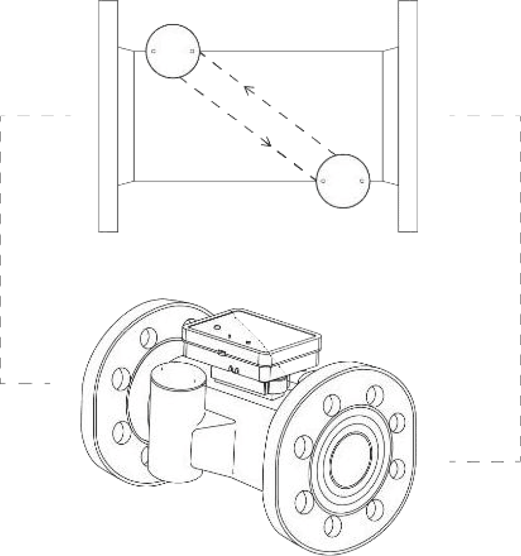
Measures and registers the volume of district heating water circulating through the pipeline in m³. It operates on the transit-time methodology, transmitting ultrasonic signals back and forth between transducers with the assistance of precision internal mirrors.
Temperature Sensor Pair
Pt1000 platinum RTD • Θ: 1 °C – 150 °C
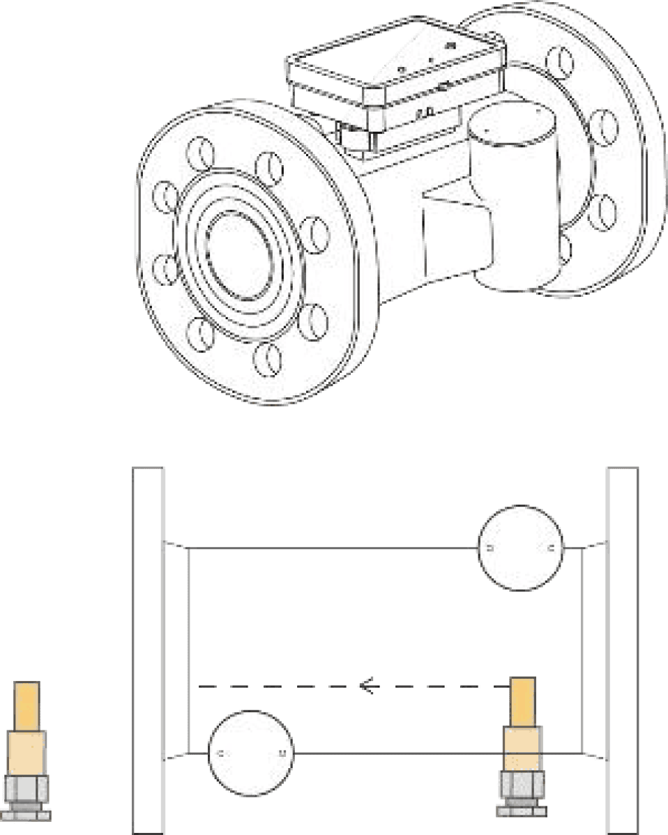
Highly sensitive Pt1000 sensors placed in the forward (flow) and return (outflow) pipes to measure thermal cooling. They are certified and calibrated as a paired set. One probe can be integrated directly into the flow sensor body, while the other is mounted in the opposite pipe.
Calculator Unit
ΔΘ: 3 K – 95 K
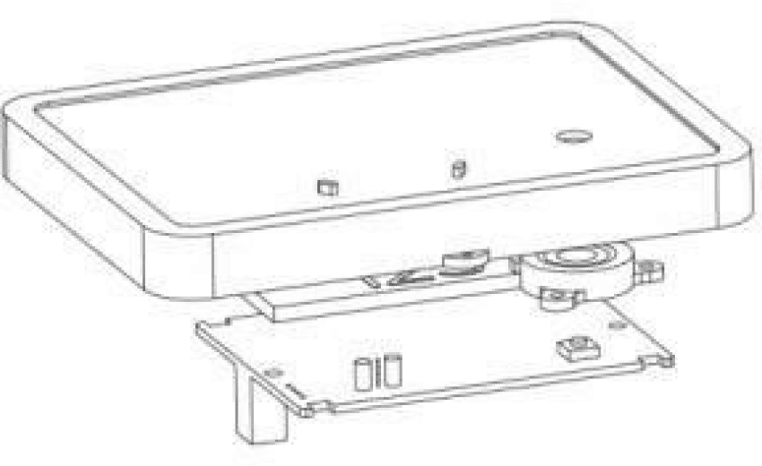
The digital microprocessor that handles energy computation. Cumulative thermal energy consumption is calculated using real-time volumetric flow measurements and temperature difference. Calibration is programmed in software at the factory. Accumulated metrics appear on the LCD and are accessible over optical or wired communication channels.
4. Installation
The installation guidelines in this section are intended to help the meter achieve its rated accuracy and to reduce the risk of damage to its internal ultrasonic components.
4.1 Pre-Installation Pipeline Flushing
Because the flow meter uses highly polished internal mirrors and sensitive acoustic transducers, the pipeline should be completely and thoroughly flushed and cleaned prior to mounting the meter. Residual weld slag, sand, rust, or construction debris left in the piping can physically scratch the mirrors, clog the flow channel, and may damage the meter.
4.2 Typical Installation Diagram & Flow Direction
Ensure the cast metal arrow on the flow sensor body aligns perfectly with the actual physical direction of the pipeline's fluid flow. The flow sensor should be installed in the direction of flow indicated by the arrow on the sensor body.
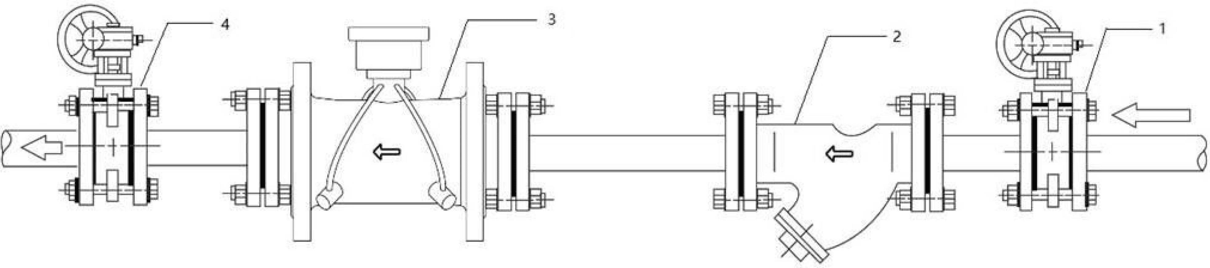
Fitted upstream so the meter body can be fully isolated for future maintenance and calibration without draining the entire heating network.
Mounted with the body arrow matching flow direction and with orientation as required by Section 5.4.
Completes the isolation pair, allowing the meter to be removed and refitted without network shutdown.
4.3 Non-Return Valve & Testing
Following physical mounting, slowly pressurize and fill the pipeline with cold water to check for leaks. Confirm that the LCD displays a positive flow volume and that registered temperatures correspond to actual physical pipeline parameters.
4.4 Interface & Communication Wiring
Every meter features an optical infrared IrDA interface, compliant with IEC 62056-21, as a factory standard on the calculator faceplate. For remote telemetry, the calculator can be ordered with one of several optional, galvanically isolated communication interfaces.
The standard wired M-Bus version is supplied with a 2-wire cable and wire end ferrules. It supports primary or secondary addressing and operates under a maximum voltage of 50 V. The cable can be extended up to several hundred metres using 2 × 0.75 mm² cable with an external distribution box.
Caution: To prevent overheating and processor malfunction, a reading frequency of once per hour is recommended.
| Wire colour | M-Bus (2-wire) | Pulse output (2-wire) | RS-485 (4-wire) |
|---|---|---|---|
| Red | M-Bus line (polarity independent) | Pulse output (+) | VCC power (5 ~ 24 VDC) |
| Black | M-Bus line (polarity independent) | GND ground (−) | GND ground (−) |
| Yellow | N/A | N/A | RS-485 'A' line |
| Green | N/A | N/A | RS-485 'B' line |
Galvanically isolated, 2 m standard cable length. Pulse parameters are fully programmable via service software. Pulse significance: 1 pulse per kWh, 1 pulse per 100 litres, or 1 pulse per 0.001 Gcal. Maximum voltage 30 V, maximum current 30 mA. Pulse length 100 ms, minimum pulse break 25 ms. Classification OC (open collector, compliant with EN 1434-2). Maximum voltage drop approximately 1.3 V at 20 mA.
For wireless Advanced Metering Infrastructure (AMI) networks, the meter supports several low-power wide-area (LPWA) options integrated directly into the calculator housing. These modules are factory-configured to optimize battery life and telemetry frequency
| Network technology | Frequency / ISM band | Network access / class | Max output power | Default interval |
|---|---|---|---|---|
| LoRaWAN | EU433, EU868, IN865, US915 | Class A (OTAA or ABP) | 12.15 – 20.0 dBm max | Every 4 hours (standard) |
| Sigfox (RCZ1) | 868 MHz (Europe / Middle East) | Standard Sigfox protocol | 16.0 dBm max | Every 6 hours (default) |
| Sigfox (RCZ2/4) | 902 / 920 MHz (Americas / APAC) | Standard Sigfox protocol | 24.0 dBm max | Every 12 hours (default) |
| 4G CAT1 | LTE bands B1/2/3/4/5/7/8/20/28/66 | Cellular narrowband | Carrier standard | Every 24 hours (default) |
5. Placement Recommendations
For best measurement performance, installation according to the following spatial and geometric guidelines is recommended. These conditions help minimize hydraulic distortion, physical stress, and air pocket formation at the ultrasonic sensors.
5.1 Climatic & Mechanical Operating Conditions
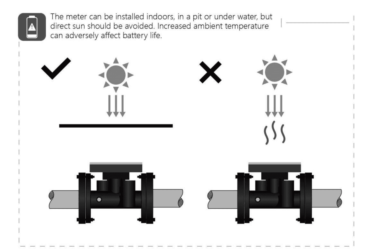
The meter is rated for indoor installation in closed, climate-controlled environments with non-condensing humidity. The rated ambient operating range is 5 °C to 55 °C. To support best performance, the pipe system should be arranged so that it does not exert mechanical stress (bending, tension, or compression) on the meter body. For harsh environments, the IP68 rating supports long-term submersion when all cable glands are securely tightened and the cover is properly fastened.
5.2 Upstream & Downstream Straight Pipe Runs
The following straight runs are recommended for best performance:
| Condition | Minimum clearance |
|---|---|
| Straight run upstream of the meter, when installed downstream of a pipe elbow | ≥ 5 × DN |
| Straight run downstream of the meter | ≥ 3 × DN |
Elbow spacing
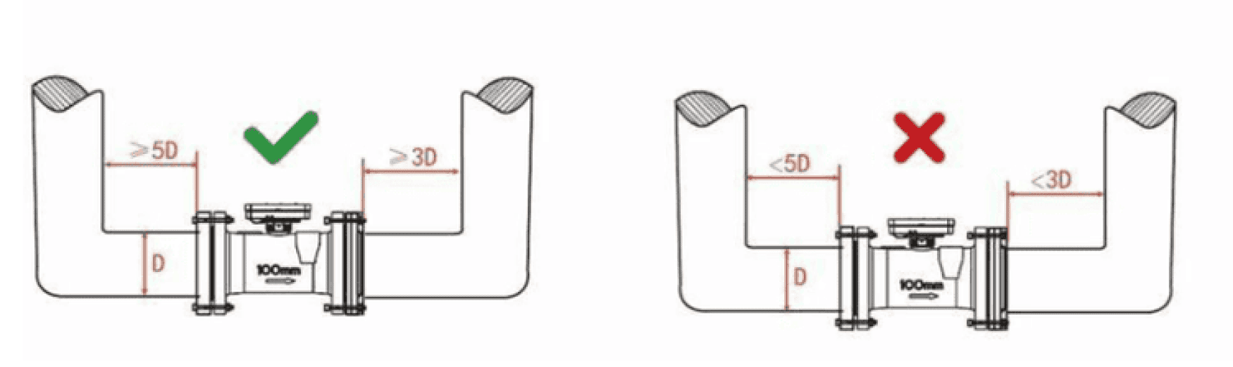
At least 5 × DN of straight pipe upstream and 3 × DN downstream.
Valve spacing
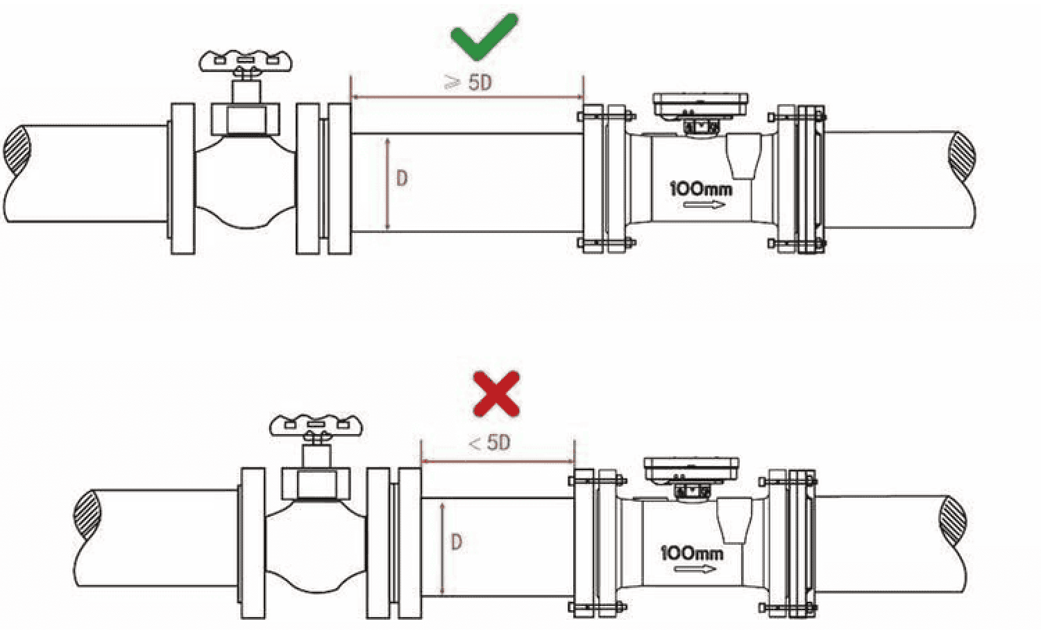
At least 5 × DN between any upstream fitting and the meter inlet.
5.3 Parallel Meter Installations
When mounting two or more meters in parallel — for example in manifold systems — maintain a minimum axis-centre distance of at least 135 mm between meters to prevent structural interference and to allow adequate servicing space.
5.4 Recommended Installation Practices
The following installation guidelines are recommended to help ensure accurate measurement. In each figure, the recommended arrangement is marked with a check and the arrangement that is not recommended is marked with a cross.
Flange welding alignment
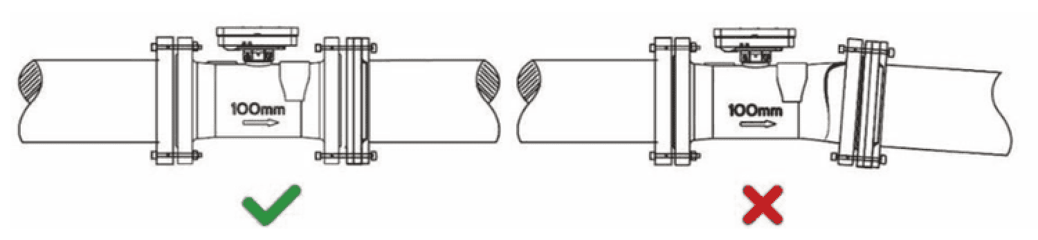
When welding pipeline flanges, do not leave excessively large gaps or weld flanges at an angle. Forcibly tightening the bolts to bridge a misaligned gap will stress the metal and can break the cast flow sensor body. If misaligned, cut and re-weld the flange before bolting.
Horizontal orientation
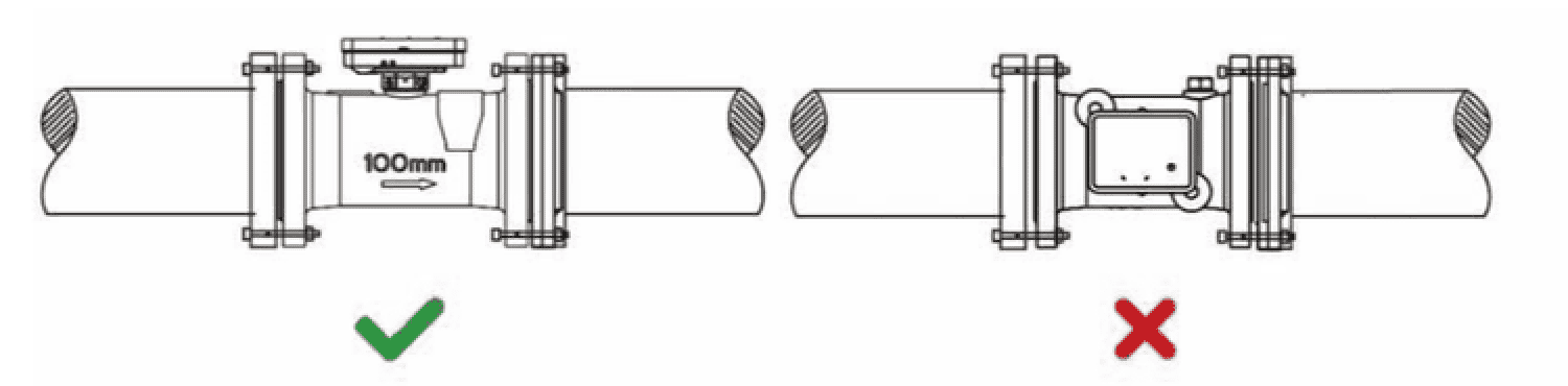
For horizontal installations, it is recommended that the calculator head point upwards. This keeps the internal acoustic transducers on the same horizontal plane. If the head faces sideways, air bubbles in the pipe may collect at the upper transducer and affect measurement.
Vertical orientation
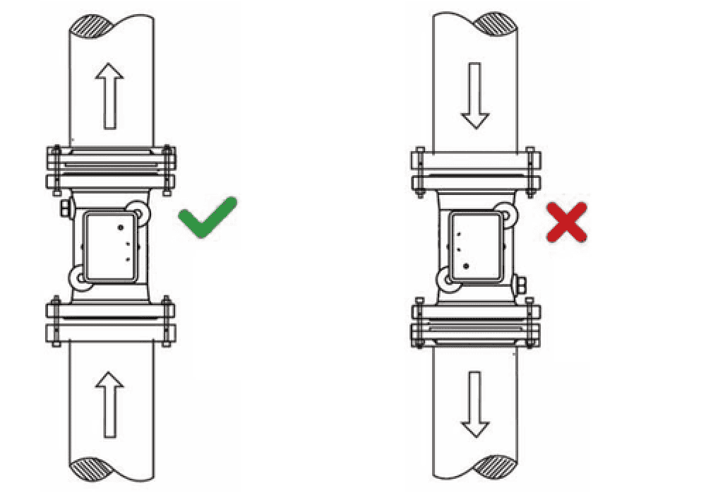
For vertical installations, it is recommended that the meter be installed with upward flow. Upward flow helps carry air out of the meter and keeps the pipe completely full of water. With downward flow, air is more likely to remain in the pipe, which can affect measurement accuracy.
U-tube installation
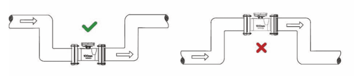
For U-tube installations, it is recommended that the meter be installed at the lowest point of the piping. Air tends to collect at high points, which can affect measurement accuracy.
6. Display & Menus
The digital calculator features a high-contrast, backlit, 8-digit LCD display that provides real-time measurement metrics, historical data, and diagnostic codes.
6.1 LCD Status Icons & Meanings
The display features several specialized icons that indicate system status, warnings, and active operational modes.
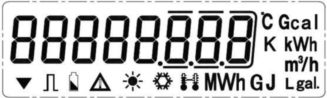
| Icon ID | Display icon | Name | Detailed functional meaning |
|---|---|---|---|
| 1 |  | Calibration mode | Indicates that the meter is in calibration mode (Menu A4). For laboratory and factory verification only. |
| 2 |  | Pulse output | Blinks to indicate active pulse output transmission. |
| 3 |  | Low battery warning | Flashes on the screen when the internal battery voltage drops to 2.7 V. Automatically disappears when voltage recovers. Battery checks occur every 30 s. |
| 4 |  | Error warning | Appears on the main screen to alert the operator that a diagnostic error code has been logged. Refer to Section 7. |
| 5 |  | Heat | Indicates that the screen is displaying accumulated heat energy consumption, selectable in kWh, MWh, or GJ. |
| 6 |  | Temperature of inflow | Indicates display of accumulated cold water consumption or real-time temperature in the inlet pipe. |
| 7 |  | In / outflow temperatures | Appears when displaying water temperatures in the forward (flow) or return (outflow) pipes. |
6.2 Button Operations & Menu Navigation
All displays are controlled with a single button on the faceplate. By default, short presses scroll through the variables in this order: supply temperature, return temperature, temperature difference, flow rate, cumulative volume, power, energy, date, time, and ID. To access the advanced configuration loops, press and hold the button for at least 5 seconds. This opens the menu selection loop (Menu A1, A2, A3, and A4). Keep holding the button to cycle through the menus, and release it to enter the selected menu.
6.3 Display Menu Architecture
The four specialized calculator loops carry the following parameters.
Menu A1 — Measurement
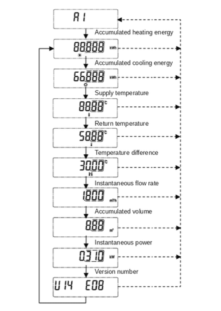
| 1.0 | Menu header A1 |
| 1.1 | Accumulated heating energy |
| 1.2 | Accumulated cooling energy |
| 1.3 | Supply temperature |
| 1.4 | Return temperature |
| 1.5 | Temperature difference |
| 1.6 | Instantaneous flow rate |
| 1.7 | Accumulated volume |
| 1.8 | Instantaneous power |
| 1.9 | Firmware number |
Menu A2 — Meter Information
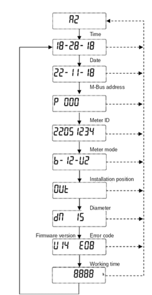
| 2.0 | Menu header A2 |
| 2.1 | Local time |
| 2.2 | Calendar date |
| 2.3 | M-Bus / meter address |
| 2.4 | Unique meter ID |
| 2.5 | Model / type ID |
| 2.6 | Installation position |
| 2.7 | Diameter & K-factor |
| 2.8 | Software version & error |
| 2.9 | Total working time |
Menu A3 — 36-Month History
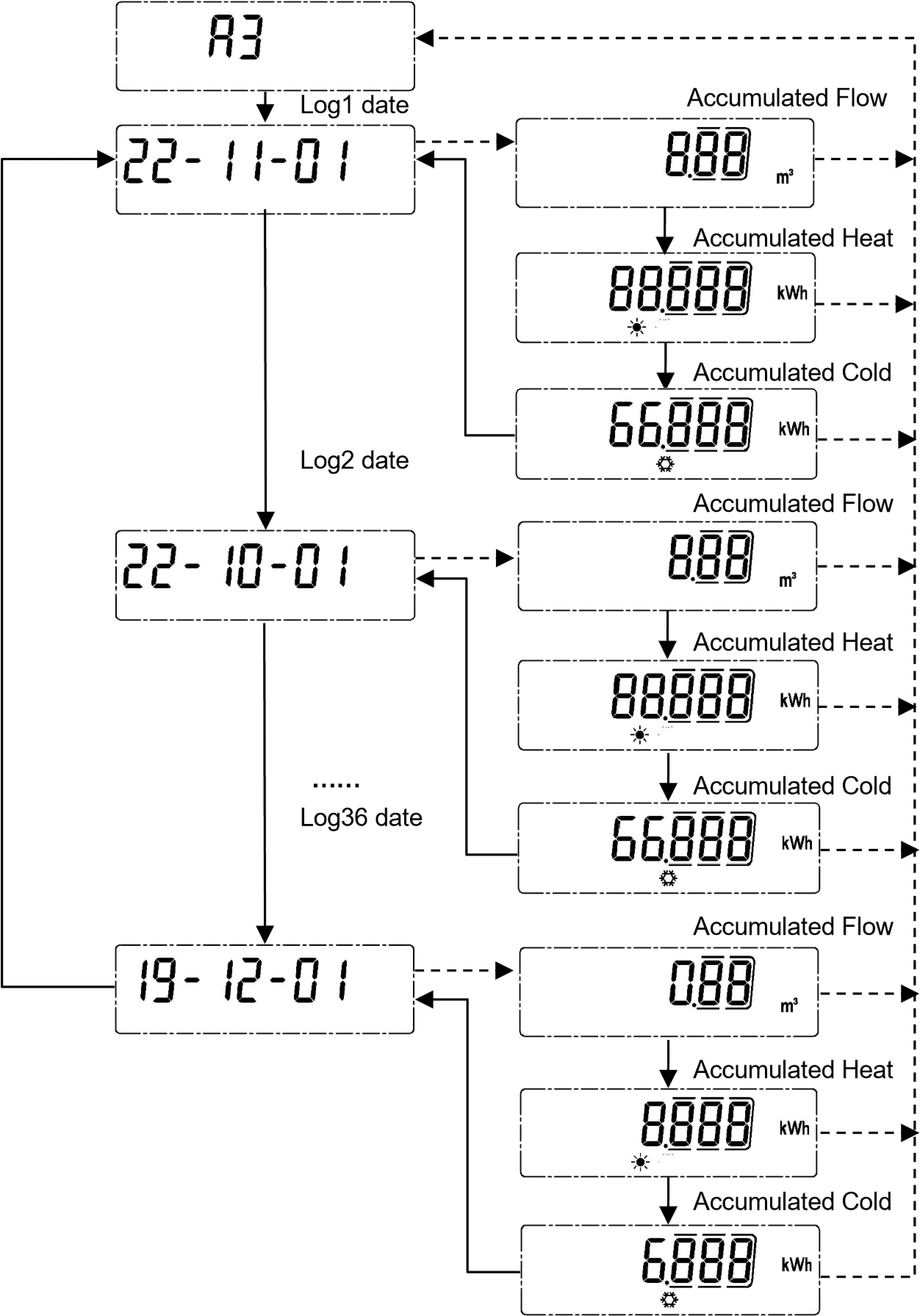
| 3.0 | Menu header A3 |
| 3.1 | Volume (end of last month) |
| 3.2 | Heat (end of last month) |
| 3.3 | Cold (end of last month) |
| 3.4 | Volume (2 months ago) |
| 3.5 | Heat (2 months ago) |
| 3.6 | Cold (2 months ago) |
| … repeating per month … | |
| 3.106 | Volume (36 months ago) |
| 3.107 | Heat (36 months ago) |
| 3.108 | Cold (36 months ago) |
Menu A4 — Calibration Mode
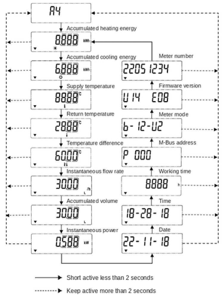
| 4.0 | Menu header A4 |
| 4.1 – 4.8 | As Menu A1 — heat, cold, temperatures, difference, flow, power |
| 4.9 | Calendar date |
| 4.10 | Local time |
| 4.11 | Accumulated working time |
| 4.12 | Meter address |
| 4.13 | Meter model / type ID |
| 4.14 | Software version |
| 4.15 | Unique meter ID |
7. Basic Troubleshooting
The integrated calculator continuously executes self-diagnosis checks. When an internal fault or operational anomaly is detected, a visual error code is immediately shown on the LCD screen, accompanied by the error warning icon.
7.1 Active Diagnostic Error Codes
| Error code | Identified meaning | Recommended corrective action |
|---|---|---|
| E01 | Low battery voltage | The battery has reached the end of its useful life. |
| E08 | Empty pipe fault | The flow sensor is not full of water. Check the pipeline to verify whether the water supply has been stopped, or whether the meter is currently in dry storage. |
| E09 | Low battery + empty pipe | Combined hardware fault. Schedule immediate service replacement of the battery and verify that water supply in the pipeline is fully restored. |
| E40 | Low temperature (below 3 °C) | The water or ambient temperature has fallen below 3 °C. Verify that the pipe has not frozen, and check environmental storage and operating temperatures. |
| E41 | Low battery + temperature below 3 °C | Combined fault. Schedule immediate battery service and check the site immediately to prevent line freezing or hardware damage. |
| E48 | Empty pipe + temperature below 3 °C | Combined fault. Check pipeline valves to ensure flow is restored, and verify that the ambient temperature is within acceptable storage limits. |
| E49 | Critical triple fault — battery + empty pipe + temperature below 3 °C | Critical system alert. Requires immediate technical dispatch to restore water flow, verify temperature controls, and replace the battery module. |
7.2 Faulty Icon Alerts
The universal fault symbol appears on the LCD screen when any of the following conditions are detected by the internal sensors:
Temperature is below 3 °C
Temperature exceeds 95 °C
Short circuit in a temperature sensor
Open circuit in a temperature sensor
Internal memory or EEPROM corruption
Empty pipe
When these errors are resolved, the icon clears on the next 30-second diagnostic cycle.
NEED HELP? Contact help@lynked.io or create a ticket here.
8. Regulatory Information
The LYKH Series is designed and manufactured to meet rigorous international quality, engineering, and metrological standards.
Standards Compliance
Built in conformity with CSA/ANSI/CAN C900, EN 1434 (thermal energy meters), and EN 13757 (communication systems for meters).
Optical interface to IEC 62056-21; pulse output classification OC per EN 1434-2.
Classes & Ratings
Environmental: Class E1 (electromagnetic, light industrial) and Class M1 (fixed installation, minimum vibration).
Metrological accuracy: Class 2, maintained over a medium temperature range of 1 °C to 150 °C and a ΔT range of 3 K to 95 K.
Trademark Notice
LoRaWAN® is a registered trademark of the LoRa Alliance.
Sigfox® is a registered trademark of Sigfox S.A.
All other trademarks are the property of their respective owners.
Looking for other LYNKED metering products?