
LYNKED Mesh RF Gateway (CG-400)
TECHNICAL MANUAL
Published July 29, 2026 • Last updated August 4, 2026 (v1.2)
1. Safety Information
2. Product Overview
2.1 Front-Access Cover
Open the front-access cover to expose the I/O connections.
2.2 Connector & Port Descriptions
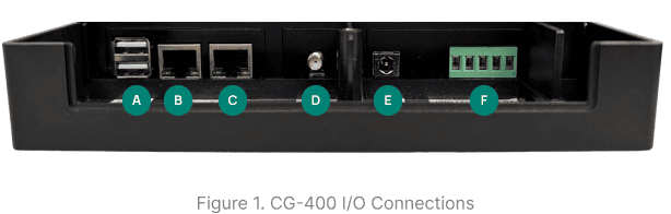
Refer to Figure 1 to locate and identify the ports described below.
This USB connector is used for debug communication and add-on devices.
This secondary Ethernet port is used for connecting to an additional network.
The primary Ethernet port. If only one Ethernet cable is used, connect it to this port.
The threaded connector for the external antenna.
24 VDC power input
This 5-pin connector supports both half-duplex and full-duplex communication. For half-duplex communication, use the pins labeled TX+ (D+) and TX- (D-). For full-duplex communication, connect TX+, TX-, RX+, RX-. Connect GND (ground) if applicable.
2.3 What's in the Box
3. Installation
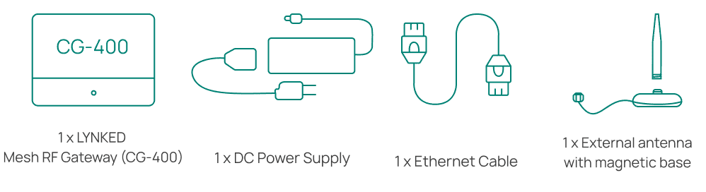
Open the box and verify that all items listed in Section 2.3 are present. If any items are missing or damaged, contact LYNKED Support immediately.
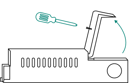
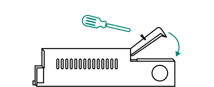
In preparation for installation and wiring, loosen the screw on the CG-400 front-access cover, then tilt the cover back to expose the I/O connections.
Choose a location that can withstand the specified operating temperature (see CG-400 Technical Specifications). Allow adequate clearance for ventilation and cable routing. Install the CG-400 in a safe location, such as a locked electrical, mechanical, or communications room or closet. Avoid unsecured areas such as hallways, stairwells, or shared amenity spaces.
For Outdoor Installations: Outdoor installation of the CG-400 is not recommended for general use. However, it may be performed in specific cases where the gateway is appropriately protected. If installed outdoors, use a NEMA-rated enclosure suitable for the local climate and environmental conditions. For information on NEMA enclosure ratings, refer to the NEMA Rating Guide.
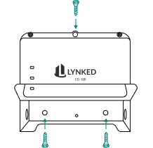
If mounting the CG-400 is required for your installation, secure it to a suitable mounting surface using three appropriate screws depending on the surface material.
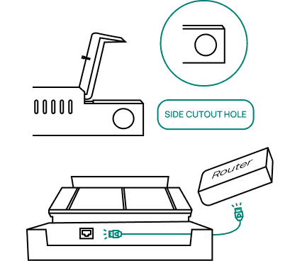
Connect one end of the provided Ethernet cable to a router or network switch, then feed the other end through the side cutout hole and connect it to the primary Ethernet port (ETH1) that is adjacent to the antenna connector.
(Optional) If dual Ethernet connectivity is required, route another Ethernet cable from the network device through the nearest cutout on the Gateway enclosure. Connect the cable to the secondary Ethernet port (ETH2), located adjacent to the USB ports.
Route the antenna cable through the side cutout hole before connecting it to the SMA connector. Verify that the connector is tightened all the way.
Mount the magnetic base of the antenna to a metal surface, such as an electrical enclosure panel or a filing cabinet, to boost the signal. Place the antenna at least 7 inches from any edge, seam, or gap in the metal. Ensure that there is 7 inches of solid metal on all sides of the base.
To achieve optimal RF coverage in the horizontal direction, the antenna should be oriented vertically (perpendicular to the ground). For optimal RF coverage in the vertical direction, the antenna should be oriented horizontally (parallel to the ground).

If RS-485 communication is required, see Section 2.2 for wiring information. Route the wires through the side cutout hole.
For RS-485 Non-Approved Devices: Do not connect non-approved devices to the RS-485 port without contacting LYNKED Inc. to verify compatibility and obtain any required licensing.
Route the power supply connector through the side cutout hole, then connect it to the CG-400.
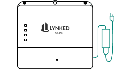
Ensure all wiring is securely connected before closing the cover to avoid having to unscrew and reopen it. Close the cover and tighten the top screw.
Ensure the power supply is plugged into a 120 VAC outlet. The CG-400 will power on, light up automatically, and take ~2 minutes to complete boot-up.
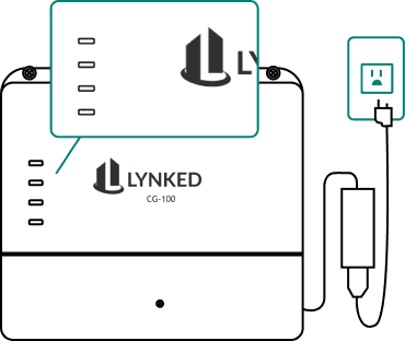
See Section 5 for LED indicator reference and basic troubleshooting.
4. Wireless Communication Overview
Mesh Topology
Nodes, repeaters, or end devices on the network can communicate directly to the CG-400. Data can also be relayed through these intermediary devices to get to the gateway.
Self-Healing
If a node, repeater, or end device drops out of the network, traffic will be automatically rerouted using the neighboring Mesh RF devices as a communication path instead.
Coverage via Mesh RF
LYNKED Mesh RF achieves extended coverage over large areas through its mesh network topology. Each device functions as a repeater, so range is extended as devices retransmit signals to one another rather than requiring a single device to reach the destination directly. This allows coverage to scale with the number of devices in the mesh, rather than being limited to the range of an individual RF device.
5. Power & LED Indicators
5.1 Power-Up Sequence
Verify all wiring connections are properly installed before applying power.
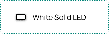

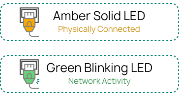
5.2 Basic Troubleshooting
Power LED is OFF
Confirm power supply is securely plugged into CG-400 and outlet.
Confirm the outlet is live or connect to a known-working outlet.
Inspect power supply for damage.
No Ethernet Activity
Check that the Ethernet cable is securely plugged in at both ends.
Confirm the router or switch port is active.
Check that the router is configured to assign IP addresses using DHCP.
Try a different Ethernet cable or port.
No Mesh RF Activity
Mesh RF connections can take over 15 minutes to establish (scanning, authentication, routing). Wait at least 15 minutes before troubleshooting further.
Confirm Mesh RF nodes, repeaters, and end devices are powered on.
If distance is degrading the signal, add a repeater device, such as the LYNKED CN-40, LYNKED CN-41, or LYNKED CM-MRFA.
Check for metal or thick concrete (especially rebar) blocking the signal path. Relocate the device or antenna to avoid the obstruction.
Mount the external antenna's magnetic base on a metal surface, such as an enclosure or filing cabinet, to boost signal.
Reorient the antenna to improve directional signal strength (see Section 3, Step 6).
Confirm the target device's MAC address is on the CG-400's authorized device list.
Ensure the antenna is fastened tightly.
NEED HELP? Contact help@lynked.io or create a ticket here.
6. Regulatory Information
6.1 Compliance
EMC: CAN ICES-003(B) / NMB-003(B), FCC Part 15B Class B
Safety: CSA C22.2 No. 62368-1, UL 62368-1
Radio Frequency (RF): RSS-Gen, RSS-102, RSS-247, FCC Part 2 (§2.1091), 15C (§15.247)
6.2 Certifications
Contains IC: 8979A-WSN27915
Contains FCC ID: UU3FC-3902-915
MET Listed:

6.3 ISED Compliance Statements
CAN ICES-003(B)
This device contains licence-exempt transmitter(s)/receiver(s) that comply with Innovation, Science and Economic Development Canada's licence-exempt RSS(s). Operation is subject to the following two conditions: (1) This device may not cause interference, and (2) this device must accept any interference, including interference that may cause undesired operation of the device.
This radio transmitter 8979A-WSN27915 has been approved by Innovation, Science and Economic Development Canada to operate with the antenna types listed below, with the maximum permissible gain indicated. Antenna types not included in this list that have a gain greater than the maximum gain indicated for any type listed are strictly prohibited for use with this device.
Allowed Antennas:
| Frequency (MHz) | Antenna Type | Maximum Gain (dBi) | Impedance (Ω) |
902-928 | Monopole | 5 | 75 |
This equipment complies with ISED radiation exposure limits for an uncontrolled environment. This equipment should be installed and operated with a minimum distance of 20 cm (8 inches) between the radiator and the user's body.
CAN NMB-003(B)
Cet appareil contient un ou plusieurs émetteurs/récepteurs sans licence conformes aux normes RSS exemptes de licence d'Innovation, Sciences et Développement économique Canada. Son fonctionnement est soumis aux deux conditions suivantes : (1) Cet appareil ne doit pas causer d'interférences, et (2) cet appareil doit accepter toute interférence, y compris les interférences pouvant entraîner un fonctionnement indésirable.
Le présent émetteur radio 8979A-WSN27915 a été approuvé par Innovation, Sciences et Développement économique Canada pour fonctionner avec les types d'antenne énumérés ci-dessous et ayant un gain admissible maximal. Les types d'antenne non inclus dans cette liste, et dont le gain est supérieur au gain maximal indiqué pour tout type figurant sur la liste, sont strictement interdits pour l'exploitation de l'émetteur.
Antennes autorisées :
| Fréquence (MHz) | Type d'antenne | Gain maximal (dBi) | Impédance (Ω) |
| 902-928 | Monopôle (détachable) | 5 | 75 |
Cet appareil est conforme aux limites d'exposition aux rayonnements d'ISED pour un environnement non contrôlé. Il doit être installé et utilisé à une distance minimale de 20 cm (8 pouces) entre l'émetteur et le corps de l'utilisateur.
6.4 UL & CSA Compliance Statements
This product is designed and manufactured to meet the safety requirements of UL 62368-1 and CSA C22.2 No. 62368-1 for Audio/Video, Information and Communication Technology Equipment. Use only the provided power supply and do not operate this equipment near water. This equipment is intended for indoor use only. Follow all instructions in this manual to ensure safe operation.
Ce produit est conçu et fabriqué conformément aux exigences de sécurité des normes UL 62368-1 et CSA C22.2 No. 62368-1 pour les équipements audio/vidéo, les équipements de technologie de l'information et de communication. Utilisez uniquement l'alimentation fournie et ne faites pas fonctionner cet équipement à proximité de l'eau. Cet équipement est destiné uniquement à un usage intérieur. Suivez toutes les instructions de ce manuel pour assurer une utilisation en toute sécurité.
6.5 FCC Compliance Statements
This device complies with part 15 of the FCC Rules. Operation is subject to the following two conditions: (1) This device may not cause harmful interference, and (2) this device must accept any interference received, including interference that may cause undesired operation.
Note: This equipment has been tested and found to comply with the limits for a Class B digital device, pursuant to part 15 of the FCC Rules. These limits are designed to provide reasonable protection against harmful interference in a residential installation. This equipment generates, uses and can radiate radio frequency energy and, if not installed and used in accordance with the instructions, may cause harmful interference to radio communications. However, there is no guarantee that interference will not occur in a particular installation. If this equipment does cause harmful interference to radio or television reception, which can be determined by turning the equipment off and on, the user is encouraged to try to correct the interference by one or more of the following measures:
Reorient or relocate the receiving antenna.
Increase the separation between the equipment and receiver.
Connect the equipment into an outlet on a circuit different from that to which the receiver is connected.
Consult the dealer or an experienced radio/TV technician for help.
Changes or modifications not expressly approved by LYNKED Inc. could void the user's authority to operate this equipment.
This device contains transmitter module FCC ID: UU3FC-3902-915.
This transmitter has been evaluated for use with a detachable monopole antenna with a maximum gain of 5 dBi. The use of any antenna not included in this list, or having a gain greater than 5 dBi, is strictly prohibited and may violate Federal Communications Commission rules.
This equipment complies with FCC radiation exposure limits for an uncontrolled environment. This equipment should be installed and operated with a minimum distance of 20 cm (8 inches) between the radiator and the user's body.
6.6 Tampering Prohibited
Unauthorized tampering, modification, or alteration of this device is strictly prohibited. Any such actions may compromise the performance, safety, or regulatory compliance of the device and may void applicable warranties, service agreements, and the user's authority to operate the equipment.
Looking for other gateways or communication devices?