
1. Regulatory Information
1.1 Compliance
EMC: CAN ICES-003(B) / NMB-003(B)
FCC 47 CFR §15.107 and §15.109
Safety: CSA C22.2 No. 62368-1
UL 62368-1
1.2 Certifications
Contains IC: 20953-RPI4B
Contains FCC ID: 2ABCB-RPI4B
MET Listed:

Federal Communications Commission (FCC) Notice:
Changes or modifications not expressly approved by LYNKED Inc. could void the user's authority to operate this equipment.
2. Product Overview
2.1 Front-Access Cover
Open the front-access cover to expose the I/O connections.

2.2 Connector & Port Descriptions
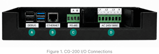
Refer to Figure 1 to locate and identify the ports described below.
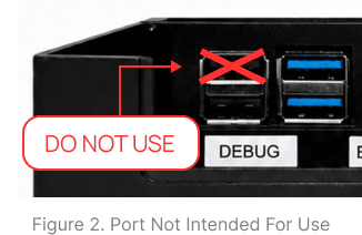
This USB connector is used for debug communication and add-on devices.
LAN interface for network communication.
The 4-pin connector supports both half-duplex and full-duplex communication. For half-duplex communication, use the two rightmost pins, labeled A (D+) and B (D-). For full-duplex communication, the pins are assigned from left to right as RX+, RX-, TX+, and TX-
This 7-pin connector powers the gateway and enables G3-PLC communication over power lines (max 240 VAC line-to-neutral). L1 (line 1) and N are required, while L2 (line 2) and L3 (line 3) are optional. All three lines support G3-PLC communication.
2.3 What's in the Box

3. Installation
Open the box and verify that all items listed in Section 2.3 are present. If any items are missing or damaged, contact LYNKED Support immediately.

In preparation for installation and wiring, loosen the screw on the CG-200 front-access cover, then tilt the cover back to expose the I/O connections.

Choose a location that can withstand the specified operating temperature (see Section 6). Allow adequate clearance for ventilation and cable routing. Install the CG-200 in a safe location, such as a locked electrical, mechanical, or communications room or closet. Avoid unsecured areas such as hallways, stairwells, or shared amenity spaces.
For Outdoor Installations: Outdoor installation of the CG-200 is not recommended for general use. However, it may be performed in specific cases where the gateway is appropriately protected. If installed outdoors, use a NEMA-rated enclosure suitable for the local climate and environmental conditions. See Section 6 for operating environment requirements. For information on NEMA enclosure ratings, refer to the NEMA Rating Guide.
If mounting the CG-200 is required for your installation, secure it to a suitable mounting surface using three appropriate screws, depending on the surface material.

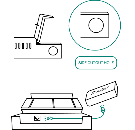
Connect an Ethernet cable to the router. Route the other end through the side cutout hole and connect it to the Ethernet port on the CG-100.
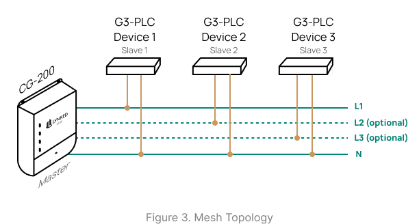
Ensure power is off and verify that all devices are de-energized before finalizing connections. Route all G3-PLC wiring through the CG-200 side cutout hole. Connect L1 and N to the G3-PLC connector (required to power the CG-200), then connect L2 and L3 only if needed for devices on those lines. See Section 2.2 for connector pin-out information and Section 5 for the wiring overview. Installations with multiple end devices connected to the same power line form a mesh network (see Figure 3).
For RS-485 Non-Approved Devices: Do not connect non-approved devices to the RS-485 port without contacting LYNKED Inc. to verify compatibility and obtain any required licensing.
Route the power supply connector through the side cutout hole, then connect it to the CG-100.

Once all connections are verified, safely energize the power lines using the appropriate method (e.g., circuit breaker, fuse, or switch). The CG-200 powers on when L1 and N are connected to power (see Section 2.1). It will take ~2 minutes to complete boot-up.
See Section 5 for LED indicator reference and basic troubleshooting.
4. Wiring Overview
G3-PLC Power
The CG-200 receives power directly from the power lines. These power lines are also used for G3-PLC communication.
Mesh Topology
The CG-200 communicates using a mesh topology (see Figure 3). End devices can communicate directly with the gateway or relay data through intermediate nodes on the same power line.
G3-PLC Wiring
G3-PLC wiring must be installed by a certified electrician and sized in accordance with applicable local and regional electrical codes.
Ethernet Connection
Connect the CG-200 to an active router using the provided Ethernet cable. Ensure the router is powered and configured to provide an IP address.
5. Power & LED Indicators
5.1 Power-Up Sequence
Verify all wiring connections are properly installed before applying power to the power lines.


5.2 Basic Troubleshooting
Power LED is OFF
Confirm all wires connected to the G3-PLC connector are securely fastened.
Verify the CG-200 is receiving power and that the circuit breaker and fuse are functional.
Confirm that L1 and N are connected on the G3-PLC connector. These pins are required to supply power to the CG-200.
No Ethernet Activity
Check that the Ethernet cable is securely plugged in at both ends.
Confirm router or switch port is active.
Check router is configured for DHCP.
Try a different cable or port.
No G3-PLC Activity
Check that the G3-PLC devices are powered on.
Verify the power line is free of electrical noise. Large motors and similar equipment can interfere with G3-PLC communication.
Inspect power line connections for corrosion.
Ensure no devices that cause electrical isolation (e.g., transformers or UPS) are installed between the CG-200 and the end devices.
Ensure surge suppression devices are not present between the CG-200 and the end devices.
NEED HELP? Contact support@lynked.io or create a ticket here.
6. Technical Specifications
Connectivity
| Interface | Specification |
|---|---|
| LAN / Ethernet | 1000 Mbps, auto-polarity correction |
| G3-PLC Port | Fully G3-PLC compliant, OFDM-based |
| RS-485 Port | Supports half/full-duplex communication |
| Default Protocols | Modbus, G3-PLC, TCP/IP |
Power
| Parameter | Specification |
|---|---|
| Input Voltage | Typical: 120 VAC Maximum: 240 VAC (line-to-neutral) |
| Input Frequency | 50 / 60 Hz |
Required Connections | L1 (line 1) N (neutral) |
Processing & Memory
| Parameter | Specification |
|---|---|
| Processor | Quad core ARM-Cortex-A72 1.5 GHz |
| Operating System | Linux |
| RAM | 1 GB SRAM |
| Flash Storage | 64 GB |
| Interval Recording | Hourly (configurable) |
Mechanical
| Parameter | Specification |
|---|---|
| Dimensions (mm) | 195 x 184 x 48.5 (L x W x H) |
| Weight | 600 g |
Operating Environment
| Parameter | Rating | Notes |
|---|---|---|
| Operating Temperature | 0°C to 60°C | Performance may be affected outside this range |
| Humidity | 0% to 95% | Non-condensing |
| Altitude | Up to 2000m | Above sea level |
| Pollution Degree | Degree 2 | For environments with non-conductive contamination and occasional condensation |