
1. Regulatory Information
1.1 Compliance
EMC: CAN ICES-003(B) / NMB-003(B)
FCC 47 CFR §15.107 and §15.109
Safety: CSA C22.2 No. 62368-1
UL 62368-1
1.2 Certifications
Contains IC: 20953-RPI4B
Contains FCC ID: 2ABCB-RPI4B
MET Listed:

Federal Communications Commission (FCC) Notice:
Changes or modifications not expressly approved by LYNKED Inc. could void the user's authority to operate this equipment.
2. Product Overview
2.1 Front-Access Cover
Open the front-access cover to expose the I/O connections.
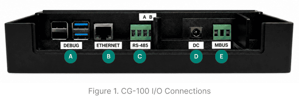

2.2 Connector & Port Descriptions
Refer to Figure 1 to locate and identify the ports described below.
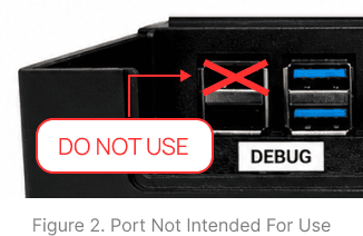
This USB connector is used for debug communication and add-on devices.
LAN interface for network communication.
The 4-pin connector supports both half-duplex and full-duplex communication. For half-duplex communication, use the two rightmost pins, labeled A (D+) and B (D-). For full-duplex communication, the pins are assigned from left to right as RX+, RX-, TX+, and TX-
24 VDC power input
The 3-pin connector is used for M-Bus wiring. The left pin is the positive voltage terminal, the center pin is not used, and the right pin is the negative voltage terminal.
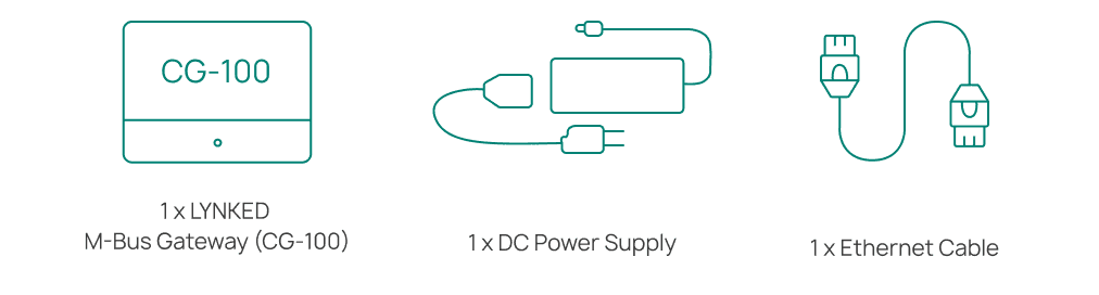
2.3 What's in the Box
3. Installation
Open the box and verify that all items listed in Section 2.3 are present. If any items are missing or damaged, contact LYNKED Support immediately.

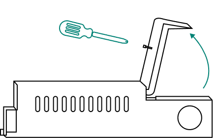
In preparation for installation and wiring, loosen the screw on the CG-100 front-access cover, then tilt the cover back to expose the I/O connections.
Choose a location that can withstand the specified operating temperature (see Section 6). Allow adequate clearance for ventilation and cable routing. Install the CG-100 in a safe location, such as a locked electrical, mechanical, or communications room or closet. Avoid unsecured areas such as hallways, stairwells, or shared amenity spaces.
For Outdoor Installations: Outdoor installation of the CG-100 is not recommended for general use. However, it may be performed in specific cases where the gateway is appropriately protected. If installed outdoors, use a NEMA-rated enclosure suitable for the local climate and environmental conditions. See Section 6 for operating environment requirements. For information on NEMA enclosure ratings, refer to the NEMA Rating Guide.
If mounting the CG-100 is required for your installation, secure it to a suitable mounting surface using three appropriate screws depending on the surface material.

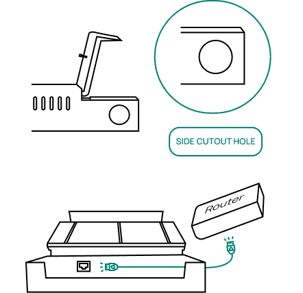
Connect an Ethernet cable to the router. Route the other end through the side cutout hole and connect it to the Ethernet port on the CG-100.
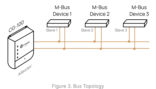
For multiple devices, connect M-Bus devices by wiring them together on a single bus (see Figure 3). Refer to the manufacturer's instructions for your M-Bus devices and connect the wiring to the MBUS connector on the CG-100. Route all M-Bus device wiring through the CG-100 side cutout hole. With all devices de-energized, connect the wires to the CG-100. See Section 2.2 for connector pin-out information and Section 4 for the wiring overview.
For RS-485 Non-Approved Devices: Do not connect non-approved devices to the RS-485 port without contacting LYNKED Inc. to verify compatibility and obtain any required licensing.
Route the power supply connector through the side cutout hole, then connect it to the CG-100.

Ensure all wiring is securely connected before closing the cover to avoid having to unscrew and reopen it. Close the cover and tighten the top screw.

Ensure the power supply is plugged into a 120 VAC outlet. The CG-100 will power on, light up automatically and will take ~2 minutes to complete boot-up.

See Section 5 for LED indicator reference and basic troubleshooting.
4. Wiring Overview
M-Bus Power
The CG-100 directly powers compatible M-Bus devices. Refer to the manufacturer's instructions for your M-Bus devices and review device-specific wiring requirements.
Bus Topology
Connect all M-Bus devices on a single bus (see Figure 3). See Section 2.1 for the M-Bus connector pin-out information.
M-Bus Wiring
Use 18 AWG wire for all M-Bus connections. Strip the wire ends to 6–8 mm before inserting them into the screw terminals.
Ethernet Connection
Connect the CG-100 to an active router using the provided Ethernet cable. Ensure the router is powered and configured to provide an IP address.
5. Power & LED Indicators
5.1 Power-Up Sequence
Verify all wiring connections are properly installed before applying power to the power lines.


5.2 Basic Troubleshooting
Power LED is OFF
Confirm power supply is securely plugged into CG-100 and outlet.
Confirm outlet is live or try a different outlet.
Inspect power supply for damage.
No Ethernet Activity
Check Ethernet cable is securely connected at both ends.
Confirm router or switch port is active.
Check router is configured for DHCP.
Try a different cable or port.
No M-Bus Activity
Check M-Bus terminal wiring uses 18 AWG wire.
Verify wiring topology is configured correctly.
Check M-Bus devices are powered on.
NEED HELP? Contact support@lynked.io or create a ticket here.
6. Technical Specifications
Connectivity
| Interface | Specification |
|---|---|
| LAN / Ethernet | 1000 Mbps, auto-polarity correction |
| M-Bus Port | EN 13757-2, screw-type terminal, up to 250 devices |
| RS-485 Port | Supports half/full-duplex communication |
| Default Protocols | Modbus, M-Bus, TCP/IP |
Power
| Parameter | Specification |
|---|---|
| Input Voltage | 24 VDC |
| Input Current | 2 A (max) |
Processing & Memory
| Parameter | Specification |
|---|---|
| Processor | Quad core ARM-Cortex-A72 1.5 GHz |
| Operating System | Linux |
| RAM | 1 GB SRAM |
| Flash Storage | 64 GB |
| Interval Recording | Hourly (configurable) |
Mechanical
| Parameter | Specification |
|---|---|
| Dimensions (mm) | 195 x 184 x 48.5 (L x W x H) |
| Weight | 510 g |
Operating Environment
| Parameter | Rating | Notes |
|---|---|---|
| Operating Temperature | 0°C to 60°C | Performance may be affected outside this range |
| Humidity | 0% to 95% | Non-condensing |
| Altitude | Up to 2000m | Above sea level |
| Pollution Degree | Degree 2 | For environments with non-conductive contamination and occasional condensation |